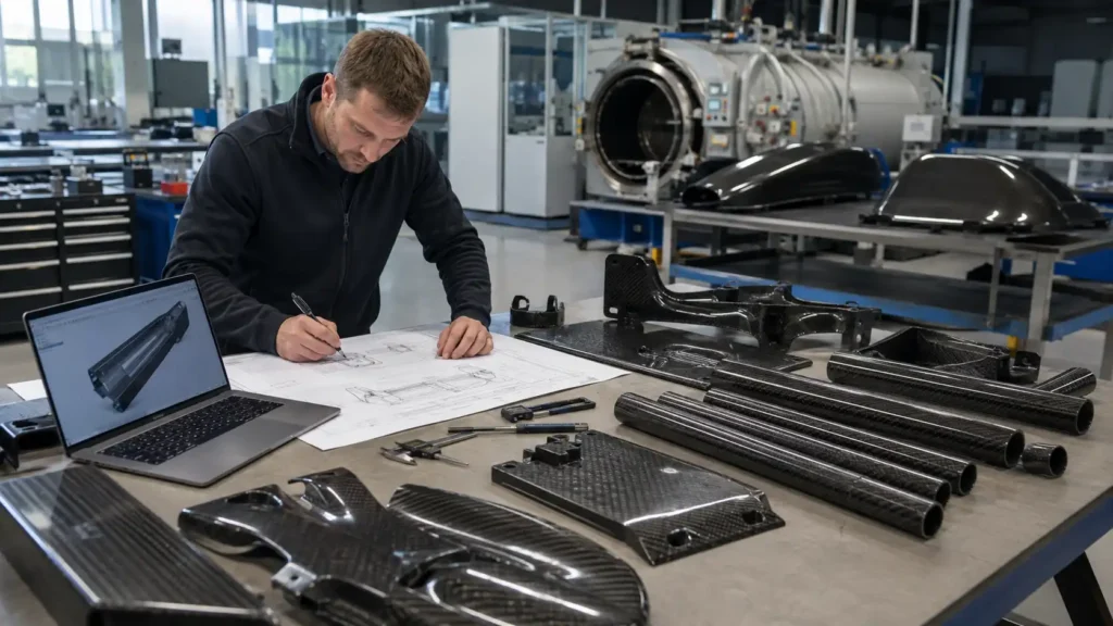
A custom carbon fiber part does not start with choosing T300, T700, prepreg, or an autoclave.
It starts with understanding what the finished component needs to do.
A customer may want to:
-
Replace an aluminum or steel part
-
Reduce weight
-
Increase bending stiffness
-
Produce a lightweight tube or plate
-
Add threaded metal connections
-
Improve corrosion resistance
-
Develop a new OEM carbon fiber product
Each of these requirements can lead to a different material, layup, tooling method, and production process.
A typical project follows this path:
Drawing Review → Process Selection → Material & Layup → Tooling → Forming & Curing → Machining → Inserts & Assembly → Inspection → Production
The important point is that these stages are connected.
A hole may require local reinforcement.
A metal insert may change the tube wall design.
A cosmetic surface may affect tooling.
A five-piece prototype may use a different production strategy from a 5,000-piece OEM order.
This guide explains how a custom carbon fiber component moves from an initial drawing to repeat production.
Custom Carbon Fiber Manufacturing Process at a Glance
| Podium | Main Decision |
|---|---|
| Drawing review | What does the part need to do? |
| Process selection | Which manufacturing method fits the geometry and volume? |
| Material selection | Which fiber and resin system are appropriate? |
| Layup design | Which fiber directions support the actual loads? |
| Gereedschap | Does the part require a mold, mandrel, or fixture? |
| Forming & curing | How should the laminate be consolidated and cured? |
| Secondary machining | Which holes, profiles, or cut lengths are required? |
| Inserts & assembly | How will the carbon fiber connect to other parts? |
| Inspectie | Which dimensions and features are critical? |
| Productie | How will the approved part be reproduced consistently? |
A reliable custom carbon fiber project should consider the complete process before production begins.
Step 1: Review the Drawing and Application
The drawing shows the geometry.
The application explains why the geometry matters.
Both are important.
Before selecting a carbon fiber manufacturing process, the supplier should understand four areas.
Dimensions and tolerances
Important information may include:
-
Totale afmetingen
-
Tube OD and ID
-
Wanddikte
-
Plaatdikte
-
Diameter van het gat
-
Positie van het gat
-
Slots and cutouts
-
Assembly dimensions
-
Critical tolerances
Not every dimension needs the same tolerance.
For example, a bearing hole or telescopic tube fit may require tighter control than a non-functional outside edge.
Over-specifying tolerance can increase machining and inspection cost without improving product performance.
Load and function
The manufacturer should know whether the part experiences:
-
Bending
-
Tension
-
Compression
-
Torsion
-
Vibration
-
Impact
-
Buckling
-
Combined loads
Carbon fiber is directional, so the layup should match the actual loading condition.
Current material
If the carbon fiber component is replacing an existing part, provide:
-
Current material
-
Current weight
-
Current dimensions
-
Existing problem
-
Streefgewicht
-
Required improvement
For example, the goal may not be to make a tube stronger.
The real goal may be to achieve similar stiffness at significantly lower weight.
Operating environment
Environmental conditions may affect the resin, surface finish, adhesives, and metal fittings.
Useful information includes:
-
Gebruik binnenshuis of buitenshuis
-
Working temperature
-
Water exposure
-
Salt exposure
-
UV exposure
-
Chemical exposure
-
Electrical requirements
The earlier these conditions are known, the easier it is to select the right material system.
Step 2: Choose the Right Manufacturing Process
There is no single best carbon fiber manufacturing process.
The correct process depends on:
-
Product geometry
-
Load
-
Vereisten inzake oppervlakte
-
Verdraagzaamheid
-
Aantal
-
Tooling budget
-
Target unit cost
A practical starting point looks like this:
| Producttype | Typical Manufacturing Route | Main Reason |
|---|---|---|
| Straight carbon fiber rod | Pultrusie | Efficient for constant profiles |
| Standard straight tube | Pultrusion or tube-forming process | Suitable for simple geometry |
| Custom structural tube | Roll wrapping or controlled tube layup | Better control of wall and fiber direction |
| Telescopische buisdelen | Custom tube production + precision finishing | OD/ID fit and straightness matter |
| Koolstofvezelplaat | Lamination / press processing | Produces flat laminate |
| CNC-plaat van koolstofvezel | Laminate + CNC machining | Suitable for complex profiles and holes |
| Curved visible part | Prepreg molding | Better control of shape and appearance |
| Complex 3D structural part | Prepreg / vacuum / molded process | Suitable for shaped components |
| Repeat molded OEM component | Compression molding where appropriate | Better production repeatability |
| Cylindrical wound structure | Filament winding where appropriate | Controlled fiber placement around an axis |
This table is a guide, not a fixed rule.
The same part may be manufactured in more than one way.
The decision should be based on performance and production economics rather than simply choosing the most expensive process.
For a deeper comparison of tube manufacturing methods, link internally to:
Pultruded vs Roll-Wrapped Carbon Fiber Tubes
Step 3: Select the Carbon Fiber and Resin System
A CFRP component consists of:
Carbon fiber + resin matrix
Both affect the finished part.
Kwaliteit van koolstofvezel
Different carbon fibers provide different combinations of:
-
Tensile strength
-
Modulus
-
Elongation
-
Processing behavior
-
Kosten
A higher fiber grade does not automatically create a better product.
For many commercial components, layup, wall thickness, geometry, and connection design can be more important than simply changing from one fiber grade to another.
Resin system
The resin affects:
-
Cure process
-
Heat resistance
-
Moisture resistance
-
Chemical resistance
-
Impact behavior
-
Surface quality
-
Production cycle
The resin should be selected for the actual operating environment.
A carbon fiber component used indoors at room temperature does not necessarily need the same resin system as a component exposed to high heat, chemicals, or continuous outdoor use.
Step 4: Design the Layup Around the Load
Carbon fiber does not behave like an isotropic metal.
Fiber direction matters.
Typical orientations include:
-
0° fibers for lengthwise strength and bending stiffness
-
±45° fibers for torsion and shear
-
90° or circumferential fibers for transverse support and splitting resistance
-
Woven fabric for more balanced properties and visible surface appearance
The correct laminate often combines several directions.
For example, a long carbon fiber tube may need:
-
Longitudinal fibers for bending
-
Angled fibers for torsion
-
Circumferential reinforcement around clamps or inserts
This is why specifying only:
“3K carbon fiber”
does not define a structural part.
3K may describe the tow or visible weave, but it does not describe the complete laminate design.
Step 5: Decide What Tooling Is Required
Tooling has a major effect on both sample cost and production cost.
Different products require different tooling.
Carbon fiber tubes
Tube production may require:
-
Mandrels
-
Wrapping fixtures
-
Cure tooling
-
Grinding fixtures
-
Cutting fixtures
Telescopic tubes may also require additional finishing to control OD, ID, straightness, and section fit.
CNC carbon fiber plates
A flat CNC plate may not need a dedicated 3D mold.
A laminate sheet can first be produced and then CNC-cut to the final shape.
This is often practical for:
-
Beugels
-
Drone-kentekenplaten
-
Machine panels
-
Fixtures
-
Small-volume custom parts
Molded carbon fiber parts
A curved or complex component may require:
-
Mold tooling
-
Trimming fixtures
-
Drilling fixtures
-
Assembly fixtures
Tooling becomes more important as production volume increases.
Prototype Tooling vs Production Tooling
Prototype and production tooling do not always need to be identical.
A prototype may use a simpler method to verify:
-
Geometry
-
Pasvorm
-
Surface appearance
-
Gewicht
-
Montage
-
Basic function
Once the design is approved, production tooling may be optimized for:
-
Faster cycle time
-
Better repeatability
-
Easier demolding
-
Consistent hole position
-
Lower labor cost
This is why expected annual quantity should be discussed early.
A tooling method suitable for five samples may not be economical for thousands of parts.
Step 6: Lay Up and Form the Carbon Fiber
Once the tooling and laminate design are defined, the carbon fiber material is placed into or around the tool.
Depending on the process, this may involve:
-
Prepreg
-
Dry reinforcement
-
Woven carbon fabric
-
Unidirectional material
-
Chopped carbon molding material
Layers are arranged according to:
-
Fiber direction
-
Vereiste dikte
-
Local reinforcement
-
Vereisten inzake oppervlakte
Local reinforcement
Critical areas may need additional reinforcement around:
-
Holes
-
Tube ends
-
Inserts
-
Clamp areas
-
Bolted joints
-
High-load corners
Adding reinforcement only where it is needed can be more efficient than increasing the thickness of the entire part.
Cosmetic surfaces
If appearance matters, additional attention may be required for:
-
Weave alignment
-
Fabric distortion
-
Seams
-
Resin-rich areas
-
Surface pinholes
Structural and cosmetic requirements should be specified separately.
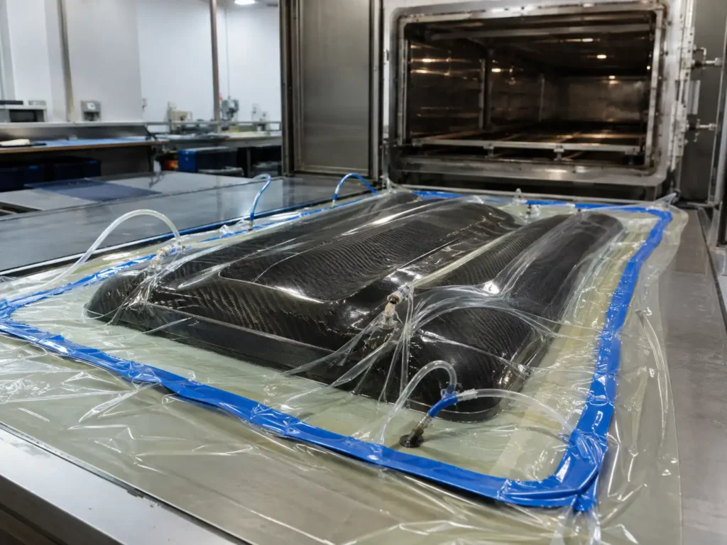
Step 7: Consolidate and Cure the Part
The laminate must then be consolidated and cured.
Depending on the material system and product, possible processes include:
-
Vacuümverpakking
-
Oven curing
-
Out-of-autoclave curing
-
Press molding
-
Compressiegieten
-
Uitharding in een autoclaaf
The manufacturing method should match the performance requirement.
Not every carbon fiber product needs an autoclave.
For many industrial, sports, outdoor, and commercial parts, other controlled processes may provide the required performance at a more reasonable cost.
The better question is not:
“Is autoclave the best process?”
It is:
“Which process provides the required quality and consistency for this product?”
Step 8: Trim and Finish the Carbon Fiber Part
After curing, the part is removed from the tooling.
Secondary finishing may include:
-
Flash removal
-
Edge trimming
-
Grinding
-
Schuren
-
Polishing
-
Matte finishing
-
Gloss finishing
-
Painting
-
Clear coating
For tubes, additional finishing may be needed to control:
-
Buitendiameter
-
Surface smoothness
-
Telescopic fit
-
Bonding areas
For telescopic products, functional fit is usually more important than appearance alone.
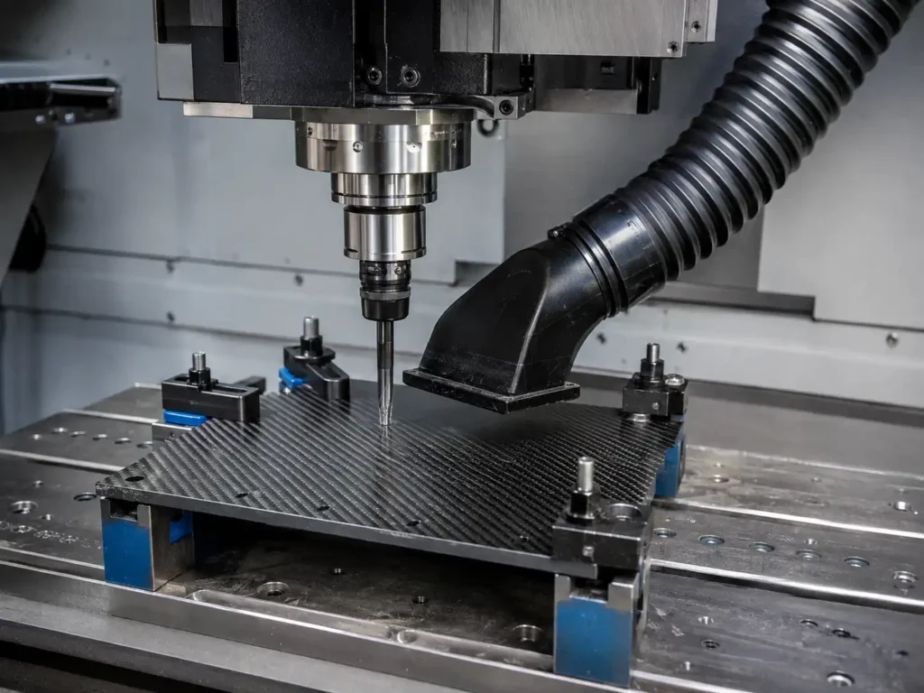
Step 9: CNC Machine Holes, Profiles, and Cutouts
Many carbon fiber parts require secondary machining after curing.
Typical operations include:
-
Cut-to-length
-
CNC profiling
-
Drilling
-
Slots
-
Cutouts
-
Verzinkboren
Examples include:
-
Drone frame plates
-
Robotic brackets
-
Equipment panels
-
Tube locking holes
-
Connector positions
Carbon fiber machining requires suitable tooling, dust control, part support, and attention to delamination.
Rather than repeating the complete machining process here, link internally to:
How to Cut, Drill, and Machine Carbon Fiber Sheets, Tubes, and Rods
Step 10: Add Metal Inserts and Connectors
Carbon fiber parts often need to connect to metal hardware.
Metal inserts may provide:
-
Threads
-
Bearing surfaces
-
Alignment
-
Replaceable hardware
-
Load-transfer points
Common materials include:
-
Aluminium
-
Stainless steel
-
Titanium
A reliable insert connection depends on:
-
Insert diameter
-
Bonding length
-
Adhesive gap
-
Surface preparation
-
Tube wall thickness
-
Load direction
-
Alignment
The connection should be designed before the final laminate is frozen.
A strong carbon fiber tube can still fail if the insert area is poorly designed.
Step 11: Inspect the Finished Part
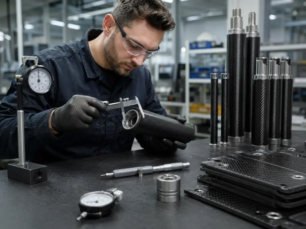
Quality control should focus on the features that affect fit, function, and repeatability.
Dimensional inspection
Typical checks may include:
-
Lengte
-
OD
-
ID
-
Wanddikte
-
Plaatdikte
-
Diameter van het gat
-
Positie van het gat
-
Overall profile
Tube-specific inspection
For tubes and telescopic components:
-
Rechtheid
-
Ovality
-
Section fit
-
Sliding performance
-
Overlap
-
Locking function
Surface inspection
Visible parts may also be checked for:
-
Pinholes
-
Fiber distortion
-
Scratches
-
Resin-rich areas
-
Uneven finish
The acceptable cosmetic standard should be defined before production.
Machining inspection
Machined parts may require checks for:
-
Hole location
-
Diameter van het gat
-
Edge quality
-
Delamination
-
Countersink quality
-
Final cut length
Insert and assembly inspection
Assembled components may require inspection of:
-
Insert position
-
Alignment
-
Thread function
-
Bond line
-
Final assembly fit
The inspection plan should follow the drawing and application rather than using the same checklist for every product.
Prototype, Pilot Batch, and Mass Production
Custom carbon fiber development normally becomes more reliable when production is divided into stages.
Prototype
The prototype is used to confirm:
-
Dimensions
-
Pasvorm
-
Gewicht
-
Uiterlijk
-
Connection method
-
Basic function
The goal is to identify problems before production tooling and fixtures are finalized.
Pilot batch
For more complex projects, a small production batch can verify:
-
Repeatability
-
Machining fixtures
-
Assembly sequence
-
Inspection standards
-
Verpakking
Mass production
Once the sample and process are approved, the focus shifts to consistency.
Production control may include:
-
Fixed material specification
-
Controlled layup
-
Approved tooling
-
Standard machining program
-
Defined inspection criteria
-
Assembly fixtures
-
Packaging requirements
An OEM customer does not only need one good sample.
The next 100 or 1,000 parts should also match the approved part.
Why Samples Cost More Than Production Parts
Sample pricing often looks high compared with production pricing.
This is because prototypes may include:
-
Engineering review
-
Gereedschap
-
CNC programming
-
Setup
-
Fixtures
-
Manual processing
-
Process adjustment
These costs are spread across only a few parts.
During production, the same fixed costs are distributed across a larger quantity.
For a useful quote, buyers should provide both:
-
Sample quantity
-
Expected production quantity
Annual demand is also helpful.
This allows the supplier to recommend a process that works for both development and production.
Common Mistakes in Custom Carbon Fiber Projects
Choosing a process before defining the requirement
Starting with:
“I need an autoclave carbon fiber part.”
is often the wrong approach.
Start with:
-
Load
-
Geometry
-
Einde
-
Temperature
-
Aantal
-
Cost target
Then select the process.
Choosing carbon fiber only by grade
Specifying T700 does not fully define the component.
Performance also depends on:
-
Lay-up
-
Resin
-
Dikte
-
Geometry
-
Verspaning
-
Connections
Copying a metal component exactly
Carbon fiber often benefits from redesign.
A carbon fiber version may use:
-
Different wall thickness
-
Larger tube diameter
-
Local reinforcement
-
Bonded inserts
-
Different connection geometry
A direct metal-to-carbon copy may not use the material efficiently.
Adding holes too late
Holes can create stress concentrations.
Critical holes should be considered during the structural design stage.
Ignoring insert loads
A threaded insert may become the highest-loaded area of the part.
Insert design should not be treated as an afterthought.
Applying tight tolerance everywhere
Precision should be used where it affects function.
Unnecessary tolerance can increase machining and inspection cost.
Designing only for the prototype
A process that works for two handmade samples may become expensive at higher quantities.
Always consider repeat production.
What Should You Send for a Custom Carbon Fiber Quote?
The best quotation starts with clear project information.
| Information | What to Provide |
|---|---|
| Producttype | Tube, sheet, plate, molded part, pole, or assembly |
| Drawing | PDF, STEP, DXF, or CAD |
| Dimensions | Overall size, OD, ID, thickness, hole locations |
| Current material | Steel, aluminum, plastic, or existing composite |
| Main load | Bending, torsion, compression, impact, vibration |
| Streefgewicht | Current and desired weight if relevant |
| Oppervlakteafwerking | Matte, glossy, woven, painted, cosmetic |
| Inserts | Material, thread, position |
| Environment | Indoor, outdoor, marine, heat, chemicals |
| Sample quantity | Initial prototype requirement |
| Productiehoeveelheid | First order quantity |
| Jaarlijkse vraag | Expected long-term volume |
If a finished drawing is not available, a dimensioned sketch or product photo can still be used for the first review.
Best File Formats
| File Format | Optimale toepassing |
|---|---|
| STEP / STP | 3D molded components and assemblies |
| DXF | CNC-cut plates and 2D profiles |
| PDF drawing | Dimensions, tolerances, notes |
| CAD file | Detailed engineering definition |
| Photo | Existing product or reference part |
| Dimensioned sketch | Early-stage product concept |
For production, a controlled drawing is preferable to relying only on email descriptions.
How LH Carbon Solutions Supports Custom Carbon Fiber Projects
LH Carbon Solutions manufactures custom carbon fiber tubes, sheets, rods, plates, telescopic components, and drawing-based composite parts for B2B applications.
Projects may begin with:
-
A finished drawing
-
An existing metal component
-
A physical sample
-
A product photo
-
A weight-reduction target
-
A new product concept
Depending on the project, available manufacturing and secondary processing may include:
-
Op maat gemaakte koolstofvezelbuizen
-
Koolstofvezelplaten en -vellen
-
Application-based layup
-
Prepreg processing
-
Vacuum processing
-
Molded components
-
CNC-snijden
-
Drilling
-
Bonded metal inserts
-
Threaded fittings
-
Surface finishing
-
Telescopic tube matching
-
Prototype production
-
Repeat OEM manufacturing
The manufacturing route should be selected around the product rather than forcing every component into the same process.
What We Need to Review Your Project
For an initial review, send:
-
Drawing, STEP, DXF, or product photo
-
Main dimensions
-
Toepassing
-
Current material
-
Main load or current problem
-
Vereisten inzake oppervlakte
-
Sample quantity
-
First production quantity
-
Estimated annual demand
If some information is not available yet, a sketch and basic dimensions are enough to begin the discussion.
FAQ About Custom Carbon Fiber Manufacturing
How are custom carbon fiber parts made?
The process normally includes drawing review, process selection, material and layup design, tooling, forming and curing, trimming, machining, assembly, and inspection.
The exact route depends on geometry, performance, and production quantity.
What is the best carbon fiber manufacturing process?
There is no single best process.
Pultrusion, roll wrapping, prepreg molding, vacuum processing, compression molding, filament winding, and CNC machining are suitable for different product types.
Does every carbon fiber part need an autoclave?
Nee.
Autoclave curing is suitable for certain high-performance applications, but many commercial CFRP parts can be manufactured using controlled oven, vacuum, press, or out-of-autoclave processes.
What is carbon fiber layup?
Layup describes how carbon fiber layers are arranged inside the component.
The number of layers and fiber directions are selected according to load, thickness, geometry, and performance requirements.
Do custom carbon fiber parts always need a mold?
Nee.
Complex 3D parts often require molds, while many flat CNC parts can be produced from carbon fiber laminate without dedicated 3D tooling.
Can carbon fiber be CNC machined after curing?
Ja.
Carbon fiber can be cut, drilled, routed, slotted, and countersunk after curing using suitable tooling and dust control.
Can metal inserts be bonded into carbon fiber?
Ja.
Metal inserts are commonly used for threads, bearings, connectors, and assembly points.
The insert geometry, bonding length, adhesive, and surrounding laminate should match the required load.
Should I make a prototype before production?
For most new custom components, a prototype or small validation batch is recommended to confirm dimensions, fit, appearance, assembly, and basic function.
Why are carbon fiber samples expensive?
Samples often include tooling, engineering, setup, CNC programming, fixtures, and manual processing costs that are spread across only a small number of parts.
What files should I send for a quote?
STEP files are useful for 3D parts, DXF for CNC-cut profiles, and PDF drawings for dimensions and tolerances.
A photo or dimensioned sketch can also be used for an initial review.
Afsluitende gedachten
Custom carbon fiber manufacturing is not simply a molding process.
The finished component depends on a chain of connected decisions:
Application → Geometry → Material → Layup → Process → Tooling → Curing → Machining → Assembly → Inspection
A high-grade carbon fiber cannot compensate for a poor layup.
A good laminate can still fail around a badly designed hole.
A strong tube can still have a weak insert connection.
And an expensive manufacturing process does not automatically create a better product.
The best approach is to begin with the finished component and work backward.
If you already have a drawing, send the STEP, DXF, or PDF together with the application and expected quantity.
If you are replacing steel, aluminum, or plastic, also provide the current material, weight, and the problem you want the carbon fiber version to solve.
That information makes it possible to choose a manufacturing process that works not only for the first sample—but also for repeat OEM production.
